Figure 3 8 Materials Investigation 1 Packet Continued
7.1.3.8 Packet Tracer – Investigate Unicast, Broadcast, and Multicast Traffic – Instruction Answers
Oct 27, 2019 Last Updated: Oct 28, 2019 CCNA 1 Labs - Packet Tracer
7.1.3.8 Packet Tracer – Investigate Unicast, Broadcast, and Multicast Traffic Instructor Version
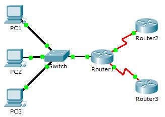
Topology

7.1.3.8 Packet Tracer – Investigate Unicast, Broadcast, and Multicast Traffic
Objectives
Part 1: Generate Unicast Traffic
Part 2: Generate Broadcast Traffic
Part 3: Investigate Multicast Traffic
Background / Scenario
This activity will examine unicast, broadcast, and multicast behavior. Most traffic in a network is unicast. When a PC sends an ICMP echo request to a remote router, the source address in the IP packet header is the IP address of the sending PC. The destination address in the IP packet header is the IP address of the interface on the remote router. The packet is sent only to the intended destination.
Using the ping command or the Add Complex PDU feature of Packet Tracer, you can directly ping broadcast addresses to view broadcast traffic.
For multicast traffic, you will view EIGRP traffic. EIGRP is used by Cisco routers to exchange routing information between routers. Routers using EIGRP send packets to multicast address 224.0.0.10, which represents the group of EIGRP routers. Although these packets are received by other devices, they are dropped at Layer 3 by all devices except EIGRP routers, with no other processing required.
Part 1: Generate Unicast Traffic
Step 1: Use ping to generate traffic.
a. Click PC1 and click the Desktop tab > Command Prompt.
b. Enter the ping 10.0.3.2 command. The ping should succeed.
Step 2: Enter Simulation mode.
a. Click the Simulation tab to enter Simulation mode.
b. Click Edit Filters and verify that only ICMP and EIGRP events are selected.
c. Click PC1 and enter the ping 10.0.3.2 command.
Step 3: Examine unicast traffic.
The PDU at PC1 is an ICMP echo request intended for the serial interface on Router3.
- a. Click Capture/Forward repeatedly and watch while the echo request is sent to Router3 and the echo reply is sent back to PC1. Stop when the first echo reply reaches PC1.
Which devices did the packet travel through with the unicast transmission?
From PC1 to Switch1 to Router1 to Router3 and back. - b. In the Simulation Panel Event List section, the last column contains a colored box that provides access to detailed information about an event. Click the colored box in the last column for the first event. The PDU Information window opens.
What layer does this transmission start at and why?
Layer 3, because it is dealing specifically with IP and ICMP - c. Examine the Layer 3 information for all of the events. Notice that both the source and destination IP addresses are unicast addresses that refer to PC1 and the serial interface on Router3.
What two changes take place at Layer 3 when the packet arrives at Router3?
The source and destination IP addresses are flipped and the ICMP message type is now 0.
Part 2: Generate Broadcast Traffic
Step 1: Add a complex PDU.
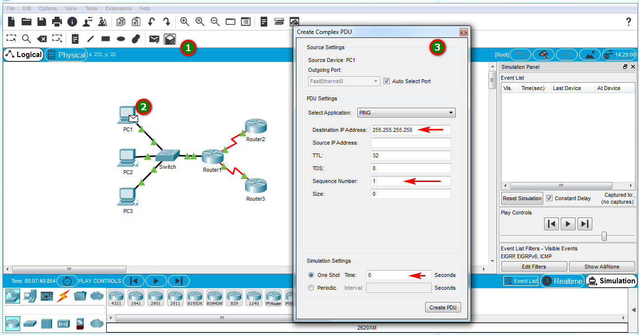
- a. Click Add Complex PDU. The icon for this is in the right toolbar and shows an open envelope.
- b. Float the mouse cursor over the topology and the pointer changes to an envelope with a plus (+) sign.
- c. Click PC1 to serve as the source for this test message and the Create Complex PDU dialog window opens. Enter the following values:
- Destination IP Address: 255.255.255.255 (broadcast address)
- Sequence Number: 1
- One Shot Time: 0

Within the PDU settings, the default for Select Application: is PING. What are at least 3 other applications available for use?
DNS, FINGER, FTP, HTTP, HTTPS, IMAP, NETBIOS, PING, POP3, SFTP, SMTP, SNMP, SSH, TELNET, TFTP and OTHER - d. Click Create PDU. This test broadcast packet now appears in the Simulation Panel Event List. It also appears in the PDU List window. It is the first PDU for Scenario 0.
- e. Click Capture/Forward twice. This packet is sent to the switch and then broadcasted to PC2, PC3, and Router1. Examine the Layer 3 information for all of the events. Notice that the destination IP address is 255.255.255.255, which is the IP broadcast address you configured when you created the complex PDU.
Analyzing the OSI Model information, what changes occur in the Layer 3 information of the Out Layers column at Router1, PC2, and PC3?
The PDU becomes a unicast replying back to PC1. - f. Click Capture/Forward again. Does the broadcast PDU ever forward on to Router2 or Router3? Why?
No. The limited broadcast should remain within the local network unless the router is set to forward. - g. After you are done examining the broadcast behavior, delete the test packet by clicking Delete below Scenario 0
.
Part 3: Investigate Multicast Traffic
Step 1: Examine the traffic generated by routing protocols.
- a. Click Capture/Forward. EIGRP packets are at Router1 waiting to be multicast out of each interface.
- b. Examine the contents of these packets by opening the PDU Information window and click Capture/Forward again. The packets are sent to the two other routers and the switch. The routers accept and process the packets, because they are part of the multicast group. The switch will forward the packets to the PCs.
- c. Click Capture/Forward until you see the EIGRP packet arrive at the PCs.
What do the hosts do with the packets?
The hosts reject and drop the packets.
Examine the Layer 3 and Layer 4 information for all of the EIGRP events.
What is the destination address of each of the packets?
224.0.0.10, the IP multicast address for the EIGRP routing protocol. - d. Click one of the packets delivered to one of the PCs. What happens to those packets?
The packets are dropped and no additional processing is done.
Based on the traffic generated by the three types of IP packets, what are the major differences in delivery?
The unicast packet moves through the network destined for a specific device, the broadcast gets sent to every device in the local area network and the multicast is sent to all devices but only processed by those that are part of the multicast group.
Download PDF & PKA file:
[sociallocker id="54558″]
[/sociallocker] 
Source: https://itexamanswers.net/7-1-3-8-packet-tracer-investigate-unicast-broadcast-and-multicast-traffic-instruction-answers.html
0 Response to "Figure 3 8 Materials Investigation 1 Packet Continued"
Post a Comment